
Modern Fluoroscopy Imaging Systems
Eric Gingold, PhD, Thomas Jefferson University, Philadelphia, PA
Updated January 2026 by Santiago Martinez-Correa, MD

Summary
Fluoroscopy, or real-time projection X-ray imaging, has been in clinical use since shortly after Roentgen’s discovery of X-rays. Early fluoroscopes consisted simply of an X-ray source and a fluorescent screen, between which the patient was placed. After passing through the patient, the remnant beam impinged upon the fluorescent screen and produced a visible glow, which was directly observed by the practitioner.
In modern systems, the fluorescent screen is coupled to an electronic device that amplifies and transforms the glowing light into a video signal suitable for presentation on an electronic display. One benefit of the modern system compared to the earlier approach is that the fluoroscopist does not need to stand in close proximity to the fluorescent screen in order to observe the live image. This results in a substantial reduction in radiation dose to the fluoroscopist. Patients receive less radiation dose as well, because of the amplification and overall efficiency of the imaging system.
Fluoroscopy differs from most other X-ray imaging in that the images produced appear in real-time, allowing evaluation of dynamic biological processes and guiding interventions. Electronic fluoroscopy systems create this perception by capturing and displaying images at a high frame rate, typically 25 or 30 frames per second (fps), with advanced systems capable of up to 60 fps or higher. At these frame rates, the human visual system cannot distinguish frame-to-frame variation and motion appears to be continuous, without visible flicker. To achieve high frame rates while keeping cumulative radiation dose to a reasonable level, the radiation dose to the image receptor per image (i.e., per frame) must be kept quite low, typically 0.01-0.1 μGy per frame, compared to 1-10 μGy for radiographic images.
Fluoroscopic images appear with an inverted grayscale (black/white is reversed) compared with standard radiographs. This convention is derivative of the appearance of the early non-intensified fluoroscopic screens, and it has been retained in the digital age even though the capability now exists to digitally reverse the grayscale at the operator’s discretion.
Introduction
A schematic of an image-intensified fluoroscopy system is shown in Figure 1. The key components include an X-ray tube with high-voltage generator, spectral shaping filters, a field restriction device (collimator), an anti-scatter grid, a digital flat-panel detector (FPD), or -in legacy systems- an X-ray image intensifier (XRII) with video camera, an image processing computer and a high-resolution display device. Ancillary but necessary components include a high-voltage generator, a patient-support device (table or couch) and hardware to allow precise positioning of the X-ray source assembly and the image receptor assembly relative to the patient.
Contemporary systems integrate artificial intelligence (AI) for real-time image enhancement, automated anatomical recognition, and procedural guidance. Dose management systems provide real-time monitoring and cumulative tracking of radiation exposure.
Figure 1. Schematic Diagram of a fluoroscopic system using an X-ray image intensifier (XRII) and video camera
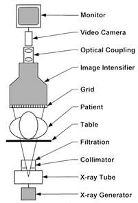
Reprinted from RadioGraphics;20(4), Schueler BA, The AAPM/RSNA physics tutorial for residents general overview of fluoroscopic imaging – Fig 2, p1117, 2000, with permission from RSNA.
X-ray Source
The high-voltage generator and X-ray tube used in most fluoroscopy systems are similar in design and construction to tubes used for general radiographic applications, but with enhancements for continuous or high-frame rate operation. For special purpose rooms such as those used for cardiovascular imaging, extra heat capacity is needed to allow angiographic “runs,” sequences of higher-dose radiographic images acquired in rapid succession to visualize opacified vessels. These runs are often interspersed with fluoroscopic imaging in a diagnostic or interventional procedure, and the combination can result in a high demand on the X-ray tube.
Focal spot sizes in fluoroscopic tubes can be as small as 0.3 mm (for high spatial with lower output) and as large as 1.0 or 1.2 mm when higher power is needed. Modern systems predominantly use pulsed radiation output rather than continuous, which reduces motion blur and can lower patient dose. Pulse widths typically range from 3-20 milliseconds depending on the clinical application.
Automatic exposure rate control (AERC) maintains the radiation dose per frame at a predetermined level, adapting to the attenuation characteristics of the patient’s anatomy and maintaining a consistent level of image quality throughout the examination. Advanced algorithms utilize anatomical recognition and region-of-interest detection to optimize image quality throughout the examination while minimizing dose. Some systems now incorporate AI-based exposure prediction to anticipate needed technique adjustments before image quality degrades.
Beam Filtration
Modern fluoroscopic imaging systems are equipped with sophisticated spectral shaping filters between the X-ray tube exit port and the collimator. Added aluminum and/or copper filtration can reduce skin dose at the patient’s entrance surface, while a low kVp produces a spectral shape that is well-matched to the barium or iodine k-edge for high contrast in the anatomy of interest.
Filtration is often automated based on real-time beam attenuation measurements, patient size estimation, and procedural requirements. The system continuously optimizes the balance between image quality and dose reduction. Some advanced systems incorporate spectral beam shaping that adjusts filtration dynamically throughout the procedure.
In addition to beam shaping filters, many fluoroscopy systems have “wedge” filters that are partially transparent to the X-ray beam. These moveable filters attenuate the beam in regions selected by the operator to reduce entrance dose and excessive image brightness.
Collimation
Shutters that limit the geometric extent of the X-ray field are present in all X-ray equipment. In fluoroscopy, the collimation may be circular (in legacy XRII systems) or rectangular in shape (in FDP systems), matching the shape of the image receptor.
When the operator selects a field of view, the collimator blade positions automatically move under motor control to be just a bit larger than the visible field. When the source-to-image distance (SID) changes, the collimator blades adjust to maintain the field of view and minimize “spillover” radiation outside of the visible area. This automatic collimation exists in both circular and rectangular field of view systems.
Advanced systems incorporate virtual collimation overlays on the live fluoroscopic image, allowing operators to preview and adjust collimation digitally before applying it, reducing the need for repeated adjustments and associated radiation exposure.
Patient Table and Pad
Patient tables must provide strength to support patients and are rated by the manufacturer for a particular weight limit, typically 200-500 kg depending on the system design. The table must not absorb excessive radiation to avoid shadows, loss of signal and loss of contrast in the image.
Carbon fiber technology offers a good combination of high strength and minimal radiation absorption, making it an ideal table material for modern systems. The radiation transmission through carbon fiber tables typically exceeds 85-90% at diagnostic energies. Foam pads are often placed between the patient and the table for added comfort, designed with minimal radiation absorption and optimized radiolucency.
Anti-Scatter Grid
Anti-scatter grids are standard components in fluoroscopic systems, since a large percentage of fluoroscopic examinations are performed in high-scatter conditions, such as in the abdominal and cardiovascular regions. Typical grid ratios range from 10:1 to 15:1 in modern systems, with higher ratios providing better scatter rejection at the cost of increased primary beam attenuation. Grids may be circular (XRII systems) or rectangular (FPD systems) and are often removable by the operator.
Image Receptor — X-ray Image Intensifier (XRII)
While XRII have been largely superseded by FDP in new installations, many legacy systems remain in clinical use. The XRII (Figure 2) is a vacuum tube device that converts the X-ray beam intensity pattern (aka, the “remnant beam”) into a visible image suitable for capture by a video camera and displayed on a video display monitor. The key components of an XRII are a cesium iodide (CsI) input phosphor, a photocathode, electron optics and an output phosphor.
The CsI input phosphor converts the X-ray image into a visible light image, much like the original fluoroscope. The photocathode is placed in close proximity to the input phosphor, and it releases electrons in direct proportion to the visible light from the input phosphor that is incident on its surface. The electrons are steered, accelerated and multiplied in number by the electron optic components, and finally impinge upon a surface coated with a phosphor material that glows visibly when struck by high-energy electrons. This is the output phosphor of the XRII.
In principle, one could directly observe the intensified image on the small (1” diameter) output phosphor, but in practice a video camera is optically coupled to this phosphor screen through an adjustable aperture and lens. The video signal is then displayed directly (or digitized), post-processed in a computer and rendered for display.
Figure 2. Components of an X-ray image intensifier
Reprinted from RadioGraphics;20(4), Schueler BA, The AAPM/RSNA physics tutorial for residents general overview of fluoroscopic imaging – Fig 5, p1120, 2000, with permission from RSNA.

The XRII achieves orders of magnitude more light per X-ray photon than a simple fluorescent screen. This occurs through electronic gain (amplification by the electron optics) and minification gain (concentrating the information from a large input surface area to a small output phosphor area) as shown in Figure 2. This allows relatively high image quality (signal-to-noise ratio) at modest dose levels compared with non-intensified fluoroscopy.
The use of video technology added an important convenience factor — it allows several people to observe the image simultaneously and offers the ability to record and post-process fluoroscopic image sequences.
Image intensifiers are available in a variety of input diameters, ranging from about 10–15 cm up to 40 cm. The input surface is always circular and curved, a design characteristic of the vacuum tube technology from which it is constructed.
The video cameras used in XRII systems were originally vidicon or plumbicon analog devices borrowed from the broadcast television industry. In later systems, digital cameras based on charge-coupled device (CCD) image sensors or complementary metal oxide semiconductor (CMOS) technology came into common use.
Image Receptor — Flat Panel Detector (FPD)
FPDs have become the dominant image receptor technology in modern fluoroscopy, having largely replaced XRII in new installations since the mid-2010s. FPDs offer numerous advantages including superior image quality, compact form factor, and elimination of geometric distortion artifacts inherent to XRIIs.
Contemporary FPDs consist of an array of individual detector elements (pixels) that are square, typically 100-200 microns per side, fabricated using amorphous silicon thin-film technology on glass substrates. A cesium iodide (CsI) scintillation layer is deposited onto the amorphous silicon substrate. The CsI is grown in columnar structures that act as light guides, directing scintillation photons to the underlying photodiodes with minimal lateral spread, thereby preserving spatial resolution.
Detector arrays used for fluoroscopy range from 20 x 20 cm up to 43 x 43 cm for the largest interventional systems. A typical large-format detector may contain 5-7 million individual detector elements. Thin-film photodiodes and transistors in each pixel capture the visible light signal from the scintillator, converting it to an electrical charge that is read out and digitized to form the digital image, which is then transferred to a computer at a frame rate selected by the user (Figure 3).
Modern FPDs achieve frame rates up to 60 frames per second or higher, with advanced systems capable of variable frame rates that can be adjusted dynamically during procedures to optimize the balance between temporal resolution and radiation dose. The electronic noise characteristics have been dramatically improved compared to early FPD designs, enabling excellent signal-to-noise ratio even at the very low dose levels required for fluoroscopy (typically 0.05-0.1 μGy per frame).
Emerging detector technologies:
Photon-counting detectors represent the next generation of fluoroscopic imaging. These detectors directly convert X-ray photons to electrical signals without an intermediate scintillation step, and can discriminate photon energies. This enables spectral (multi-energy) fluoroscopy with potential for enhanced tissue characterization and contrast agent visualization. While currently expensive and in limited clinical deployment, photon-counting technology is expected to become more prevalent in the coming years.
Figure 3. Cross-section of flat panel detector for fluoroscopic imaging
Reprinted from Radiology; 234(2), Pisano ED, Yaffe MJ, State of the Art: Digital Mammography – Fig 1, p355, 2005, with permission from RSNA.

Image Processing and Artificial Intelligence
Modern fluoroscopy systems incorporate sophisticated real-time image processing to enhance visualization and support clinical decision-making. Digital processing includes noise reduction, edge enhancement, temporal filtering, and contrast optimization applied dynamically as images are acquired.
Artificial intelligence has been integrated into fluoroscopy systems to provide capabilities that were not possible with traditional image processing. Deep learning-based noise reduction algorithms can substantially improve image quality at lower dose levels, enabling dose reductions of 30-50% while maintaining diagnostic quality. These AI algorithms are trained on large datasets of fluoroscopic images and can distinguish true anatomical signal from quantum noise more effectively than conventional filtering.
Automated anatomical recognition systems use AI to identify and label key anatomical structures in real-time, such as blood vessels, cardiac chambers, or bony landmarks. This supports navigation during interventional procedures and can trigger automated adjustments to imaging parameters optimized for specific anatomies.
AI-assisted procedural guidance includes tools for catheter tracking, automatic roadmap alignment, and predictive vessel overlay. Some systems can detect and alert operators to potential complications such as vessel perforation or contrast extravasation.
Image Display
Fluoroscopy requires high-quality video displays that allow users to appreciate fine details and subtle contrast differences in the anatomy of interest.
Modern systems feature high resolution 4K (3840 x 2160) or even 8K (7680 x 4320) flat-panel displays with high maximum luminance (typically 500-1000 cd/m²), wide color gamut, and high contrast ratios exceeding 1000:1. OLED displays are increasingly common in high-end interventional suites, offering superior contrast ratios, faster response times, and wider viewing angles compared to LCD technology. Displays should be calibrated to the DICOM Grayscale Standard Display Function (GSDF) to ensure that the full range of gray levels is visible and consistent across different displays. Quality assurance testing of display luminance, contrast, and spatial resolution should be performed regularly according to established guidelines.
The newest interventional/angiographic systems feature large-format displays up to 80-90 inches diagonal with 4K or 8K resolution. These systems support simultaneous display of multiple video inputs (20-30+ sources) that can be arranged in customizable layouts. Display configurations can be saved as presets for individual physician preferences and specific procedural types. Touchscreen functionality enables intuitive interaction with images and system controls.
System Configurations
Fluoroscopic systems are manufactured in various configurations to optimize usability for the clinical task(s) for which they are intended. The major categories include:
Radiography/Fluoroscopy (R/F) Systems: These systems consist of a patient table that can tilt from horizontal to vertical position, permitting fluoroscopy with the patient upright or at various angles. They are primarily used for gastrointestinal imaging (upper and lower GI barium studies) and genitourinary procedures. Modern R/F systems use the digital flat-panel detector for both fluoroscopy and spot radiographs, eliminating the film-based spot-film devices of older systems.
The tilting capability of the patient table allows the operator to utilize gravity to assist the movement of the barium contrast material through the gastrointestinal tract Most systems have the X-ray tube positioned under the table with the detector above, though remote-controlled configurations with inverted geometry exist to maximize operator shielding.
Cardiovascular/Interventional C-Arm Systems:
Angiographic systems employ a “C-arm” geometry to enable easy patient access as fluoroscopy guides selective arterial and venous catheter placement. These systems include advanced features like digital subtraction road mapping, stent enhancement, and 3D rotational angiography.
Modern cardiovascular systems can perform cone beam CT (CBCT) by rotating the C-arm around the patient (typically 180-200 degrees) while acquiring a sequence of projection images, then performing tomographic reconstruction to produce volumetric datasets. These 3D images are used for procedural planning, device sizing, and post-deployment assessment.
Advanced features include fusion imaging that registers and overlays pre-procedural CT or MR images onto live fluoroscopy, providing anatomical context beyond what fluoroscopy alone can show. Robotic C-arms with motorized positioning and collision avoidance are available, enabling precise, reproducible positioning and facilitating complex multi-planar imaging protocols.
Hybrid Operating Rooms:
Hybrid ORs integrate fixed interventional imaging systems (typically high-end C-arms) into surgical suites designed for procedures requiring both open surgical and minimally invasive image-guided techniques. Some hybrid rooms include intraoperative CT or combined CT-fluoroscopy systems. These environments support complex cardiovascular, neurovascular, and oncological procedures with real-time imaging guidance while maintaining surgical sterility.
Future Directions
Fluoroscopy technology continues to evolve rapidly. Several emerging technologies and trends are likely to shape the field in coming years:
Photon-counting detectors: Broader deployment enabling routine spectral fluoroscopy with enhanced tissue characterization
Advanced AI integration: Expanded use of AI for automated protocol selection, real-time quality control, complication detection, and autonomous procedural assistance
Augmented reality: More sophisticated AR systems for image overlay and navigation guidance
Robotic assistance: Integration of robotic catheter manipulation systems with fluoroscopic guidance
Ultra-low-dose protocols: Continued dose reduction through advanced image processing while maintaining or improving image quality
Enhanced fusion imaging: Real-time deformable registration of pre-procedural 3D imaging with live fluoroscopy
4D imaging: Time-resolved 3D imaging for dynamic assessment of cardiac and vascular function
Summary
Fluoroscopy has evolved from the most simplistic of non-invasive imaging methods to a very sophisticated technology with advanced 3-D capabilities, able to guide life-saving interventional procedures often with minimal patient discomfort. Many of these minimally invasive image-guided procedures have replaced highly invasive open surgical procedures. With each incremental advancement in the technology, smaller vessels and more subtle contrast differences can be visualized in real time, often with low radiation dose.
Contemporary dose management systems support the radiation safety initiatives of Image Gently and Image Wisely, providing real-time monitoring, cumulative tracking, and dose alerts. Many minimally invasive image-guided procedures have replaced highly invasive open surgical approaches, improving patient outcomes and reducing recovery times.
As technology continues to advance with photon-counting detectors, enhanced AI capabilities, and augmented reality systems, fluoroscopy will enable visualization of ever-finer vascular structures and more subtle pathology while further reducing radiation exposure to patients and staff.
References
- Schueler BA. The AAPM/RSNA physics tutorial for residents general overview of fluoroscopic imaging. RadioGraphics, 2000. 20(4):p1115-1126. Available at: http://pubs.rsna.org/doi/full/10.1148/radiographics.20.4.g00jl301115. Accessed October 23, 2014.
- Bushberg JT, Seibert JA, Leidholdt EM, Boone JM. The Essential Physics of Medical Imaging. Philadelphia, PA, Lippincott Williams & Wilkins; 3rd ed, 2012. Available at: http://books.google.com/books?id=RKcTgTqeniwC&printsec=frontcover&dq=The+Essential+Physics+of+Medical+Imaging,+3rd+Edition&hl=en&sa=X&ei=L-tIVLbCIs6zyASEioK4Bw&ved=0CDIQ6AEwAA#v=onepage&q=The Essential Physics of Medical Imaging, 3rd Edition&f=false. Accessed October 23, 2014.
- Nickoloff EL. Physics of Flat Panel Fluoroscopy Systems. RadioGraphics, 2011. 31(2):p591-602. Available at: http://pubs.rsna.org/doi/pdf/10.1148/rg.312105185. Accessed October 23, 2014.
- Pisano ED, Yaffe MJ. State of the Art: Digital Mammography. Radiology, 2005. 234(2):p353-362. Available at: http://pubs.rsna.org/doi/full/10.1148/radiol.2342030897. Accessed October 23, 2014.
- Barral M, Dohan A, Allouche C, Dautry R, Boudiaf M, Kovalev A, Correas JM, Hoeffel C, Soyer P. Artificial Intelligence in Interventional Radiology: State of the Art. European Radiology Experimental, 2024. 8(1):p45. Available at: https://link.springer.com/article/10.1186/s41747-024-00452-2. Accessed January 28, 2026.
- Chopra A, Pourmorteza A, Krishnan S, Winn AB, Ning H, Das KM, Pathak P, Kundra V. Use of Artificial Intelligence to Reduce Radiation Exposure at Fluoroscopy-Guided Endoscopic Procedures. American Journal of Gastroenterology, 2020. 115(4):p555-563. Available at: https://pubmed.ncbi.nlm.nih.gov/32195731/. Accessed January 28, 2026.
- Miller DL, Vañó E, Bartal G, Balter S, Dixon R, Eccles S, Koenig TR, Mauro MA, Schueler B. Occupational Radiation Protection in Interventional Radiology: A Joint Guideline of the Cardiovascular and Interventional Radiology Society of Europe and the Society of Interventional Radiology. Cardiovascular and Interventional Radiology, 2010. 33(2):p230-239. Available at: https://link.springer.com/article/10.1007/s00270-009-9756-7. Accessed January 28, 2026.
- Tacher V, Radaelli A, Lin M, Geschwind JF. How I Do It: Cone-Beam CT during Transarterial Chemoembolization for Liver Cancer. Radiology, 2015. 274(2):p320-334. Available at: https://pubs.rsna.org/doi/full/10.1148/radiol.14131925. Accessed January 28, 2026.
